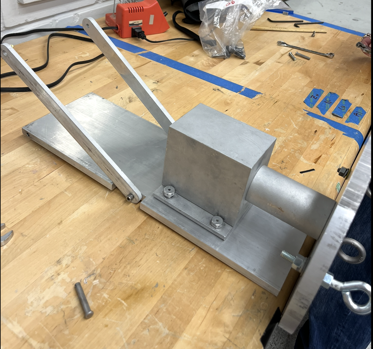
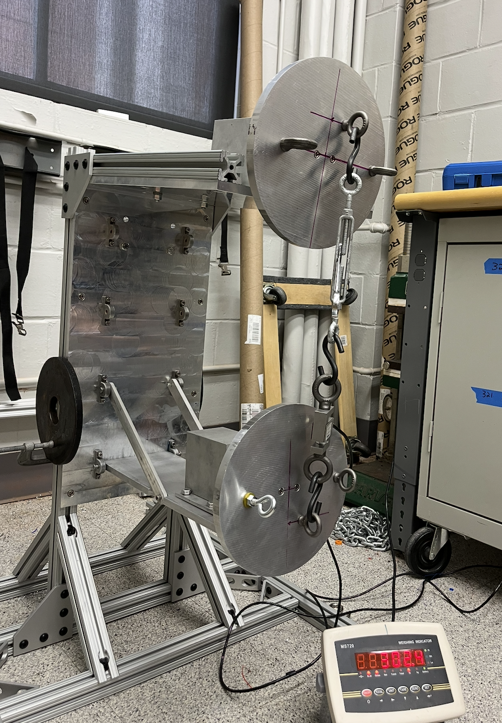
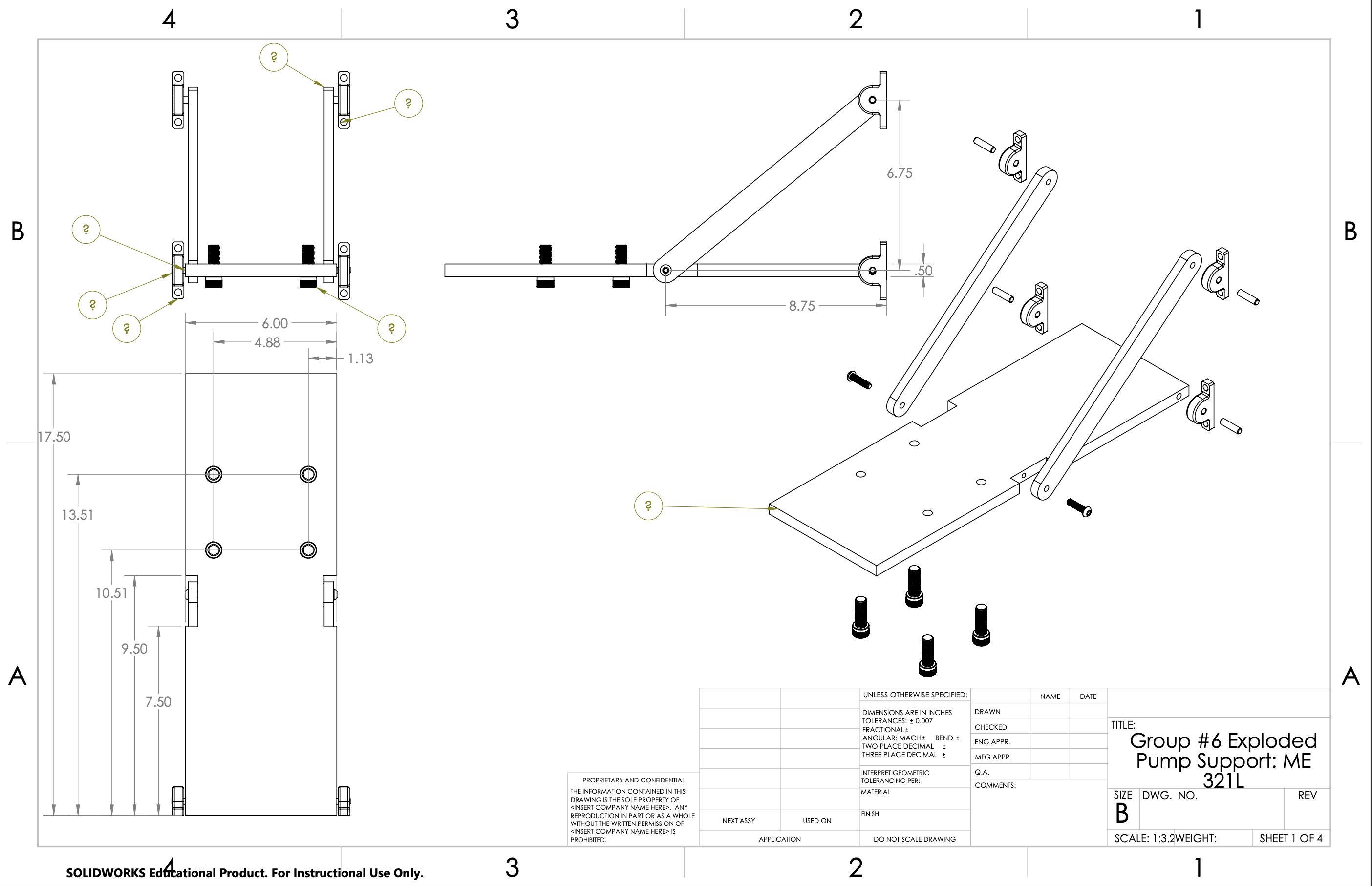
Pump Platform Assembly
Centrifugal pump support structure with analytical and computational optimization
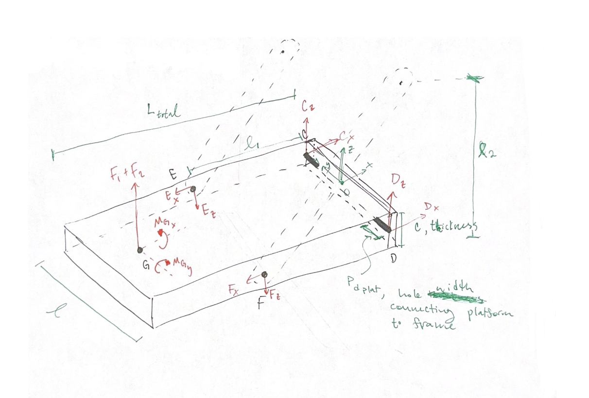
Performed analytical stress and deflection calculations using equilibrium equations, shear/moment diagrams, and Mohr's Circle to evaluate combined loading conditions
Developed and implemented Python scripts to automate dimension optimization, calculate safety factors, and generate shear/moment diagrams
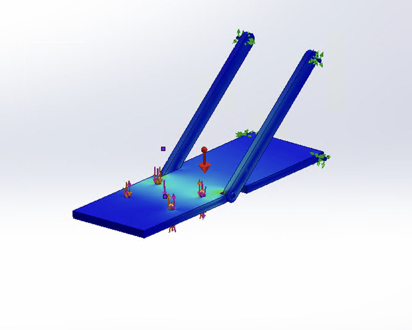
Conducted finite element analysis (FEA) in SolidWorks by first establishing boundary conditions with fixed supports at the base mounting points (shown by green constraint arrows) and applying realistic pump loads and moments (shown by red force vectors). The simulation computed stress distributions and deflections across the entire structure.
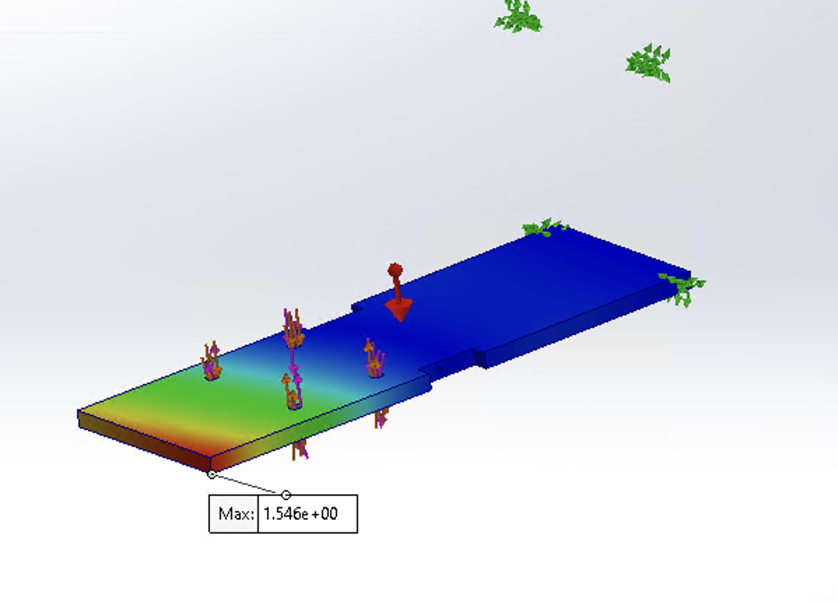
Analyzed FEA results to identify maximum deflection of 1.546 units in the platform, visualized through color-coded heat maps ranging from blue (minimal deflection) to red (maximum deflection). This validated that the design remained within acceptable deflection limits under operating loads.
Applied material selection optimization in Ansys Granta, balancing strength, corrosion resistance, and machinability to finalize component materials
Iteratively refined the design through simulation-driven iterations, reducing unnecessary thickness and verifying safety factors against yielding, buckling, and deflection limits
About This Project
Designed and optimized a centrifugal pump support structure by combining analytical calculations, Python-based automation, material selection tools, and finite element analysis to validate stresses, deflections, and safety factors, ultimately refining the design through simulation-driven iterations.
Key Features
- Performed analytical stress and deflection calculations using equilibrium equations, shear/moment diagrams, and Mohr's Circle to evaluate combined loading conditions
- Developed and implemented Python scripts to automate dimension optimization, calculate safety factors, and generate shear/moment diagrams
- Conducted finite element analysis (FEA) in SolidWorks by first establishing boundary conditions with fixed supports at the base mounting points (shown by green constraint arrows) and applying realistic pump loads and moments (shown by red force vectors). The simulation computed stress distributions and deflections across the entire structure.
- Analyzed FEA results to identify maximum deflection of 1.546 units in the platform, visualized through color-coded heat maps ranging from blue (minimal deflection) to red (maximum deflection). This validated that the design remained within acceptable deflection limits under operating loads.
- Applied material selection optimization in Ansys Granta, balancing strength, corrosion resistance, and machinability to finalize component materials